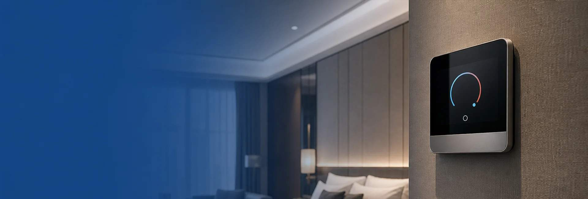
Path A· FCU water system
Upscale new build—2/4-pipe FCU module to fan coil valves; Welcome/away/window policies from RCU.
- Modules:FCU 2-pipe/4-pipe
- Linkage: same scene table ascard power,lighting
- Suited: central plant, domestic upscale new build
Thermostats, fan coils and comfort scenes linked to card power and occupancy.
* Temperature values are engineering examples; contract should state “confirm per owner energy standard and mock-up room measurement.”
Cite in tender docs—trigger conditions, target temp/airflow and linked subsystems; values in RCU scene config table revision.
| Scene | Trigger | FCU / VRF action | Linkage |
|---|---|---|---|
| Welcome | Card power ON / check-in | Set 22–24°C· low speed · valve open | Lighting·Shadingsame key |
| Occupied · guest adjust | Panel manual | Allow ±2°C trim (upper limit lockable) | Changes optionally report to PMS (integrator) |
| Away energy save | Card-out delay / unoccupied N min | 28°C standby · low fan · valve close optional | Enforced aftercard powerOFF |
| Window-open protect | Window sensor open / card in but window open | Close valve or low fan · optional alarm | Window sensor |
| Night / sleep | Sleep scene key / after 22:00 | 26°C· silent fan · valve hold | Withnight-path soft light |
| Checkout / vacant | Check-out / VC | Fan off · valve closed · no pre-cool/heat | Card power cut · optional cleaning scene |
2-pipe FCU/4-pipeper water system.
Open/close valve + 3 fan speeds; card power linkage in RCU.
Modbus / proprietary registers delivered with BOM.
Domestic upscale new build, central chilled/hot water.
VRF moduleto brand outdoor unit protocol.
Confirm brand model and tested protocol version before contract.
Welcome/away setpoints still issued by RCU.
VRF retrofit, no central plant.
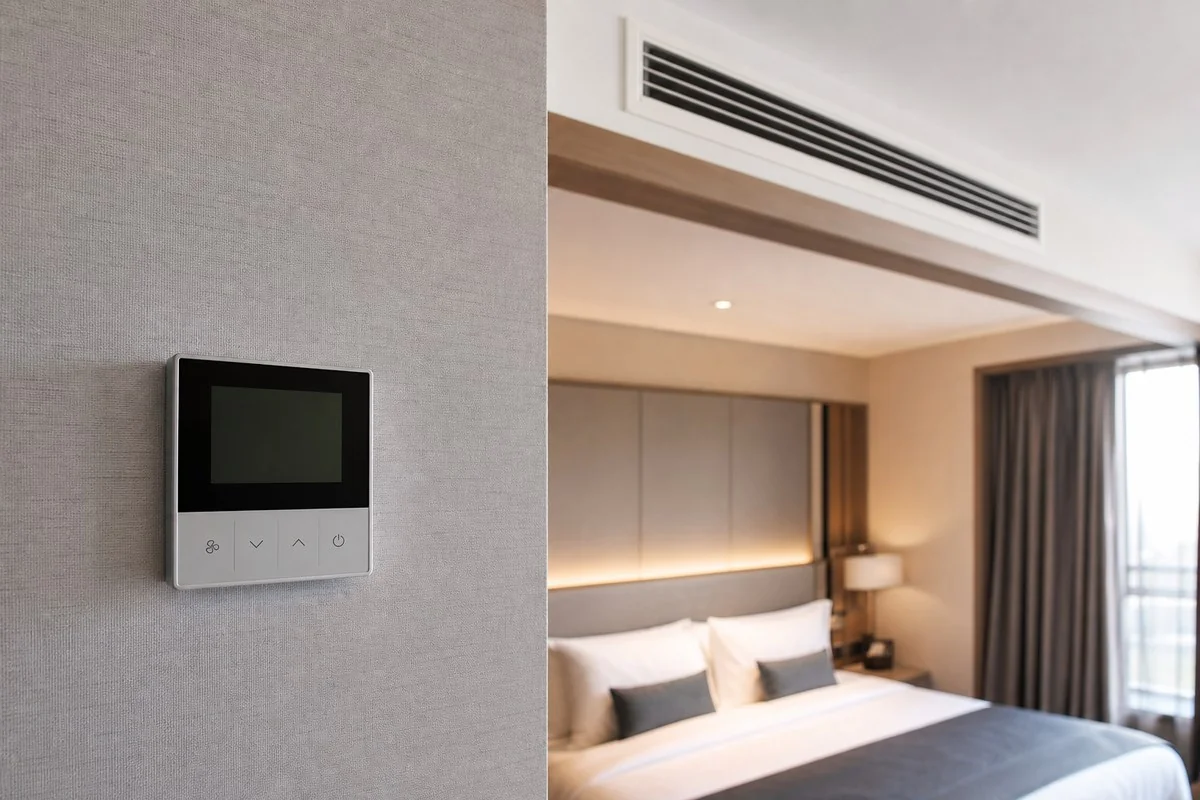
Standard thermostatshows room and set temp.
LCD thermostatfor upscale finish.
Lock upper temp, hide mode keys—prevent guest tampering.
Bedside “sleep” triggers HVAC night policy.
| # | Point | Notes | Model |
|---|---|---|---|
| 1 | Door contact | Window-open protect input | Sensors |
| 2 | Card power | Away energy trigger | Card power solution |
| 3 | Thermostat | FCU/VRF · Welcome/away presets | Thermostat panel·FCU module |
| 4 | Bedside | Sleep scene linkage | Lighting·Shading |
| 6 | RCU | Scene engine | RCU catalog |
| Comparison | FCU water system | VRF multi-split |
|---|---|---|
| Typical property | Upscale new · central plant | Retrofit · no central plant |
| PurePoint Smart module | smart-module-hvac-fcu series | smart-module-hvac-vrf |
| Protocol risk | Low (standard valve control) | Medium (brand-dependent) |
| Card power linkage | ★★★★★ | ★★★★☆ |
| Acceptance focus | Valve position · fan speed · room temp | Brand gateway integration · mode limits |
Define water system form then module—FCU and VRF share RCU scene linkage; differ in protocol and valve control.
Upscale new build—2/4-pipe FCU module to fan coil valves; Welcome/away/window policies from RCU.
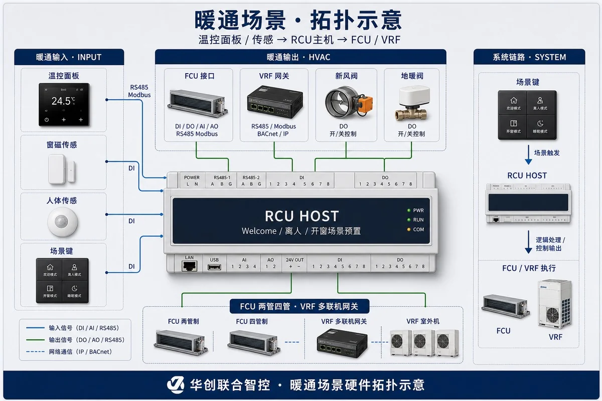
Common retrofit—VRF gateway to brand outdoor protocol; Welcome/away setpoints from RCU; panel may lock upper temp.
Per-room FCU/VRF address vs RCU channel table archived.
Welcome/away/window/sleep ×3 each; record room temp curve.
After card removal delay, HVAC enters standby limit.
RCU local scenes still run without cloud.
Updates on RCU controllers, smart panels and engineering documentation.
Product updates, project references and industry news by email.
Wiring diagrams, BOM lists, Modbus/API docs and field guidance.