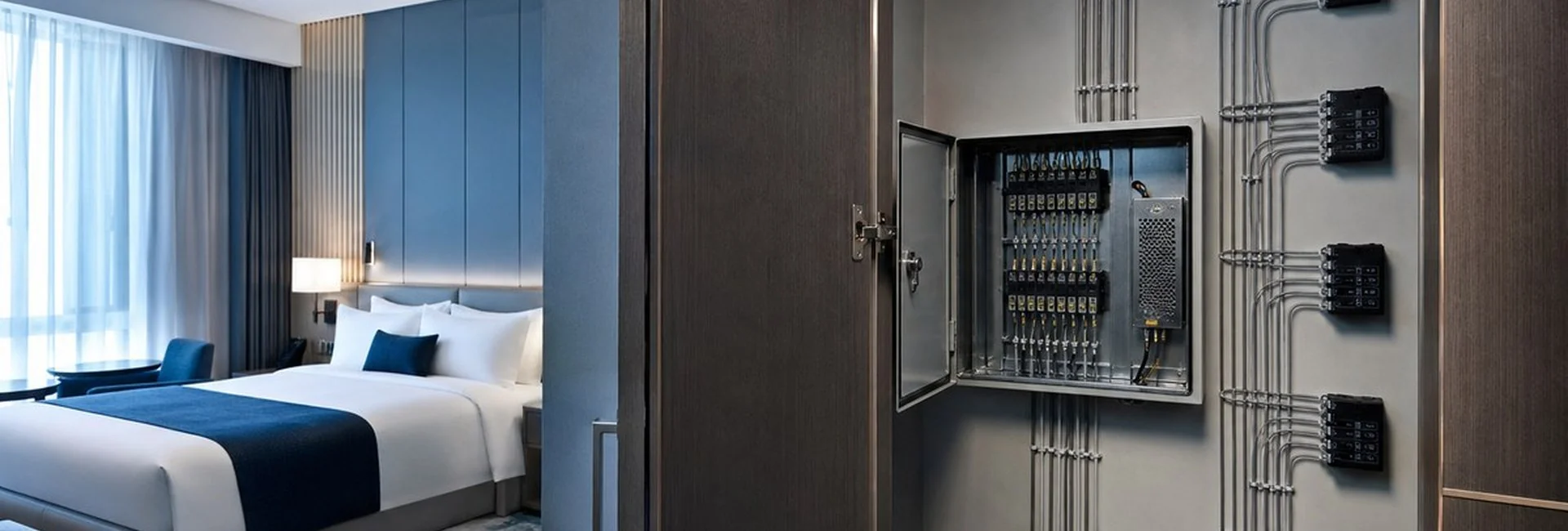
① Gateway load&zoning
Deploy one wireless RCU gateway per room or floor; plan subnets by wall material and distance; suites and connecting rooms get separate gateways or repeaters.
Wireless hotel RCU retrofit — Mesh / ZigBee gateways with wireless panels and card-power modules; minimal wall damage for renovation hotels.
* Schedule and load figures are engineering ranges; tender docs should state "subject to mock-up room and low-voltage survey".
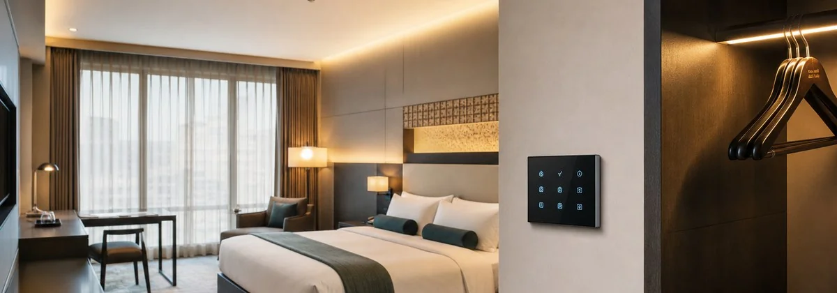
For tenders, fix networking and power before panel silk-screen — table below reflects PurePoint Smart wireless project conventions; models per signed BOM revision.
Deploy one wireless RCU gateway per room or floor; plan subnets by wall material and distance; suites and connecting rooms get separate gateways or repeaters.
Battery keys suit minimal wall opening; live/neutral wireless suits always-on scene keys. Bedside and entry per contract branch selection.
Wireless saves low-voltage runs only; card power, HVAC, and curtain motor mains circuits follow single-room wiring diagrams; relay modules in enclosure.
Welcome, vacant, and card-power linkages stored locally on gateway/host; room execution unaffected offline; upper system sync optional.
Switch by property type — for tender "technology route" chapter and closure plan; compare withwired solution.
| Comparison | Wireless RCU | Wired RCU | Hybrid (wired backbone + wireless endpoints) |
|---|---|---|---|
| Schedule | Interleaved with fit-out; low-voltage 5–10 days/floor | Full fit-out low-voltage 15–25 days/floor | 12–18 days/floor |
| Cabling | Gateway power + minimal runs to box; panels wireless | Star low-voltage to each panel | Riser bus + wireless bedside/bath |
| Best for | Boutique chains, tight-schedule new build | Full-fit luxury, stability priority | Standard room wired + suite wireless extension |
| Risk | Wall shielding needs survey; battery O&M | Chase cost and schedule | Two protocol doc sets to align |
| Comparison | Wireless RCU | Wired RCU | RS485 bus retrofit |
|---|---|---|---|
| Schedule | 0.5–1 day/room; 3–5 days/floor | Chasing 5–8 days/floor | Conduit 4–6 days/floor |
| Cabling | Gateway near LV box; wireless card power/panels | Full-room low-voltage rewire | Single bus + module addresses |
| Best for | Legacy hotels, economy upgrades | Full renovation, floor closure OK | Chain standard stores with existing conduits |
| Risk | Metal partitions affect signal; budget battery swaps | Revenue loss from closure | Address conflicts and terminal matching |
| Comparison | Wireless RCU | Panel swap only (keep existing wiring) | Modular chassis add-on |
|---|---|---|---|
| Schedule | 2–3 days/room (no full-floor closure) | 1–2 days/room | 3–4 days/room (add circuits) |
| Cabling | Add gateway + wireless modules; mains unchanged | Reuse existing low-voltage | Swap modules in box; minor LV adjustment |
| Best for | B&B, boutique rooms, mock-up first | Legacy system OK, UI upgrade only | Need more circuits for HVAC/curtains |
| Risk | Coexistence with legacy needs VLAN isolation | Features limited by legacy host | Enclosure space and cooling |
Aligned withhotel parent 6-point template; table lists typical PurePoint Smart subsystems for wireless deployment, for point diagrams.
| # | Single-room point | Wireless engineering note | PurePoint Smart subsystem |
|---|---|---|---|
| 1 | Door sensor · doorbell | Wireless door sensor or DI to gateway; DND/MUR dry contacts | Door sign solution |
| 2 | Entry triple panel | Wireless card power / keyless door-sensor power + scene keys | Card power solution |
| 3 | Thermostat | Wireless thermostat panel or FCU module via gateway | HVAC solution |
| 4 | Bedside panel | Multi-key wireless scene switch (battery or live/neutral) | Lighting solution |
| 5 | Desk info panel | Always-on outlet independent; optional wireless info keys | Info panels |
| 6 | RCU host | Wireless RCU gateway+ relay expansion modules | RCU catalog |
| Comparison | Wireless RCU | Wired guestroom control system |
|---|---|---|
| Use case | Retrofit, B&B, tight-schedule new build | Luxury new build, stability priority |
| Install flexibility | ★★★★★ | ★★☆☆☆ |
| Stability | ★★★★☆ | ★★★★★ |
| Response speed | ★★★★☆ | ★★★★★ |
| Retrofit cost | Lower | Higher |
| O&M focus | Battery replacement, signal survey | Terminal inspection, wire labels |
| Detail | This page | Wired tech solution → |
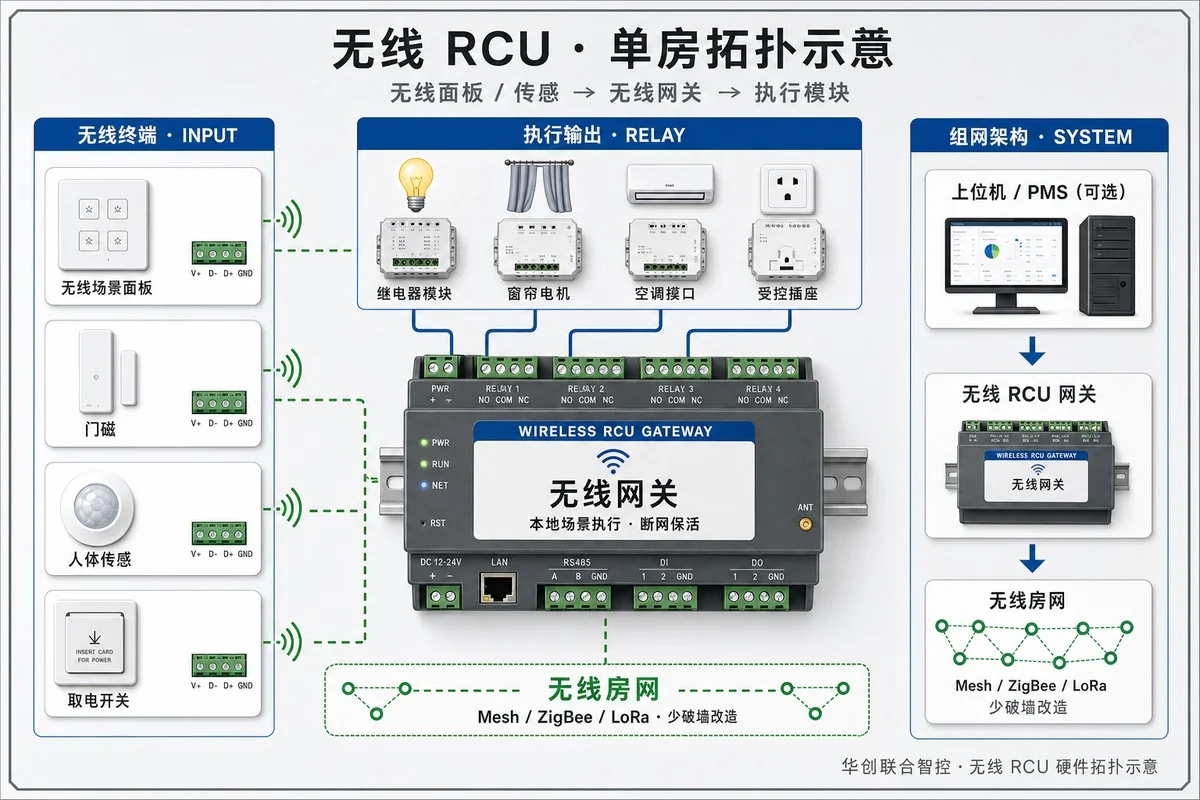
Three layers as left diagram:input layerwireless scene panels, door sensors, PIR, card-power switches → in-roomwireless gateway(local scene execution) →output layerrelay modules drive curtains, HVAC, and controlled outlets.
PurePoint Smart primarily deliverslower two hardware layers: gateway, wireless terminals, relay modules, and terminal tables; excludes PMS, mini-program, and group cloud software.
Input wireless terminals → in-room wireless gateway → output relays/modules → lighting, HVAC, curtain mains; optional uplink to integrator gateway / PMS. PurePoint Smart delivers gateway-to-terminal hardware and docs; software by integrator.Engineering docs download →
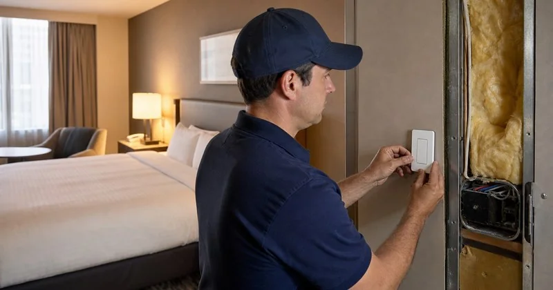
Measure RSSI in mock-up room; log metal door frames and elevator-adjacent rooms; add repeaters or live/neutral panels if needed.
LV box needs 220V and Ethernet; document gateway vs card-power main switch in scene table (vacant room gateway may standby).
Tender lists battery model and replacement cycle; test card permissions, card power, and full scene chain.
Test Welcome, card-out delay, DND door sign 3× each; attach toenergy-savingacceptance pack.
Updates on RCU controllers, smart panels and engineering documentation.
Product updates, project references and industry news by email.
Wiring diagrams, BOM lists, Modbus/API docs and field guidance.