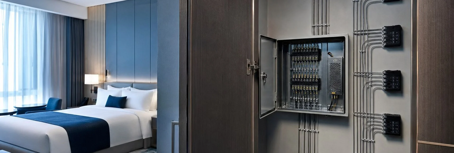
Star low-voltage · per-room isolated
Panels, card power, door sensors, thermostats home-run to one RCU; no cross-room chaining; faults isolated per room for electrician and contractor troubleshooting.
Star wiring to the RCU host per room — wiring tables for new-build and high-spec projects.
* Wire gauge, cores, and terminal IDs per signed wiring atlas; table is PurePoint Smart engineering summary for tender docs and point diagrams.
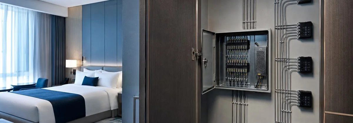
Unlike wireless retrofit — wired fixes topology inconstruction phase, stability and maintainability inoperations.
Panels, card power, door sensors, thermostats home-run to one RCU; no cross-room chaining; faults isolated per room for electrician and contractor troubleshooting.
Multi-circuit lighting, curtains, card power driven by RCU relays/dimmers; Welcome, sleep, night paths preset on host, no cloud dependency.
Bedside, entry, desk use standard 86 boxes; key/scene table in factory config; chain stores clone silk and logic.
Join at LV riser and conduit stage; one-time wiring long-term use; suited to international luxury and reliability-first projects.
Switch by property type — for tender "technology route" and closure plan; compare withwireless solution.
| Comparison | Wired guestroom control system | Wireless RCU | RS485 bus |
|---|---|---|---|
| Schedule | Full fit-out low-voltage 15–25 days/floor | Interleaved with fit-out, 5–10 days/floor | 12–18 days/floor |
| Cabling | Star low-voltage to each panel | Gateway power + wireless panels | Single bus + module addresses |
| Best for | Full-fit luxury, stability priority | Tight-schedule new build / boutique chain | Chain standard room batch replication |
| Risk | Chase cost and schedule | Wall shielding needs survey | Address conflicts and terminal matching |
| Comparison | Wired guestroom control system | Wireless RCU | Hybrid (wired backbone + wireless endpoints) |
|---|---|---|---|
| Schedule | Chasing 5–8 days/floor | 0.5–1 day/room; 3–5 days/floor | 4–6 days/floor |
| Cabling | Full-room low-voltage rewire | Gateway near LV box; wireless card power/panels | Riser bus + wireless bedside/bath |
| Best for | Full renovation, floor closure OK | Legacy hotels, economy upgrades | Standard room wired + suite wireless extension |
| Risk | Revenue loss from closure | Metal partitions; battery O&M | Two protocol doc sets to align |
| Comparison | Wired guestroom control system | Panel swap only (keep existing wiring) | Modular chassis add-on |
|---|---|---|---|
| Schedule | 5–7 days/floor (chasing required) | 1–2 days/room | 3–4 days/floor (add circuits) |
| Cabling | Add star low-voltage to new points | Reuse existing low-voltage | Swap modules in box; minor LV adjustment |
| Best for | Mock-up first, partial floor closure | Legacy system OK, UI upgrade only | Need more circuits for HVAC/curtains |
| Risk | Conflict with existing conduits | Features limited by legacy host | Enclosure space and cooling |
Aligned withhotel parent 6-point template; typical PurePoint Smart subsystems for star wired deployment.
| # | Single-room point | Wired engineering note | PurePoint Smart subsystem |
|---|---|---|---|
| 1 | Door sensor · doorbell | RVV 2×0.75 to RCU DI; DND/MUR dry contacts | Door sign solution |
| 2 | Entry triple panel | Card power + scene keys; RELAY + DI to RCU | Card power solution |
| 3 | Thermostat | RS485 shielded pair or HVAC module dry contacts | HVAC solution |
| 4 | Bedside panel | RVV 6×0.75 to PANEL-BUS; scene | Lighting solution |
| 5 | Desk info panel | RVV 4×0.75; always-on outlet independent | Info panels |
| 6 | RCU smart host | Wired RCU host+ relay / dimmer modules | RCU catalog |
Select by property — wired emphasizesstability and circuit expansion, wirelessretrofit schedule; same 6-point BOM types, different networking and modules.
| Comparison | Wired guestroom control system | Wireless RCU guestroom control |
|---|---|---|
| Wiring form | Star low-voltage to RCU host | Gateway + wireless panels/modules, minimal cabling |
| Construction window | New build / full fit-out with structure | Existing retrofit, short schedule, minimal wall opening |
| Scene response | ★★★★★ local relays, low latency | ★★★★☆ gateway and battery maintenance |
| Circuit expansion | Relay/dimmer modules as needed | Limited by wireless points and gateway capacity |
| Troubleshooting | Terminal table + wire numbers, electrician-friendly | Gateway logs + module pairing |
| Typical project | Luxury new build, full-fit business hotel | Legacy retrofit, B&B economy |
| PurePoint Smart docs | This page wiring table ·wiring atlas | Wireless tech solution → |
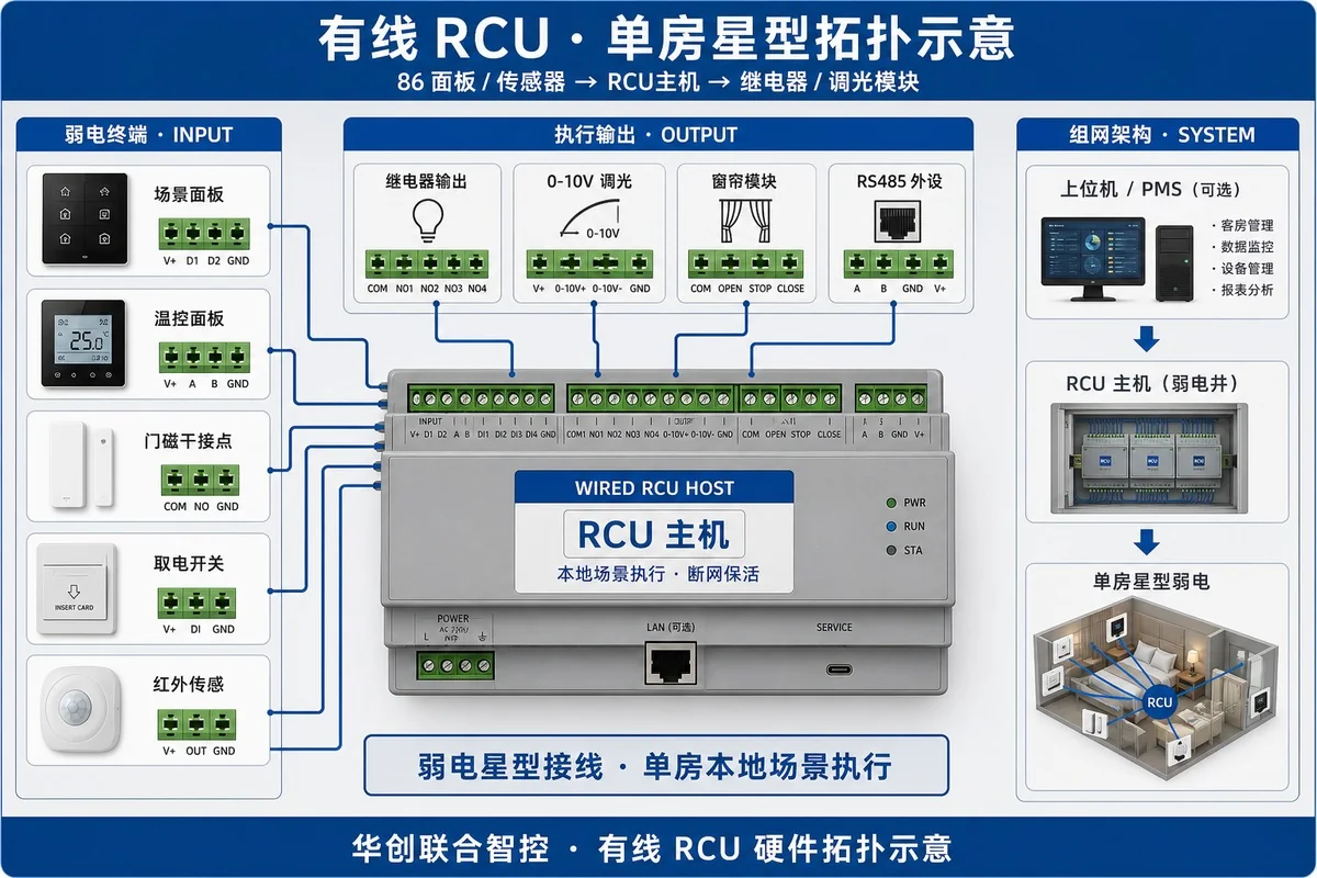
Panels, card power, door sensors, thermostatsstar home-runto RCU host — per-room isolated, no cross-room chaining; relay modules drive mains circuits centrally.
PurePoint Smart deliversRCU to terminal hardware: host, 86 panels, card power modules, relays, andsingle-room star wiring table; excludes PMS, mini-program, group cloud.
Core referencefor wired guestroom control — tender docs, LV drawings, and acceptance lists use this structure; wire numbers, conduit size, and RCU terminals in project wiring atlas.
| Point | Cable type | RCU connection | Notes |
|---|---|---|---|
| Door sensor · doorbell | RVV 2×0.75 mm² | DI-01 / DI-02 | Normally-closed door sensor; doorbell dry contact shares LV riser withdoor sign DND/MUR |
| Entry triple · card power | RVV 4×0.75 mm² | RELAY-01 + DI-03 | Card power contacts control main/sub circuits; seecard power logic |
| Thermostat | RVSP 2×0.75 mm² (shielded pair) | RS485-A/B or HVAC module | FCU / VRF; Welcome / vacant perHVAC solution |
| Left · right bedside | RVV 6×0.75 mm² | PANEL-BUS L / R | Bright / sleep / read; curtains linkmotorized shading |
| Desk triple panel | RVV 4×0.75 mm² | PANEL-BUS-03 | Desk lamp, outlets, USB; same key map asinfo panel |
| RCU smart host | RVV 3×1.5 mm² + star hub | LV riser / wardrobe access | Local scene persistence; open protocol ·model catalog |
| Point | Cable type | RCU connection | Notes |
|---|---|---|---|
| RCU master · living room | RVV 3×1.5 mm² | LV riser | Suite master RCU; connecting rooms may use dual masters |
| Entry card power | RVV 4×0.75 mm² | RELAY-01 | Whole-suite card power main logic |
| Living room scene panel | RVV 6×0.75 mm² | PANEL-BUS-01 | Receive / cinema / all-off |
| Master / second bedroom panels | RVV 6×0.75 mm² ×2 | PANEL-BUS-02 / 03 | Sleep / night / curtain zones |
| Dimmer modules | RVV 4×0.75 mm² | DIM-01–04 | Strip, wall, mood zones |
| Sub RCU (optional) | RVV 4×0.75 mm² | Bedroom remote hub | When circuits >28 add ·modular chassis |
* Wire gauge, cores, and terminal IDs per signed wiring atlas; chain projects lock BOM revision for cross-store copy.
Star LV in dedicated conduit, not shared with mains; label every terminal per wiring atlas revision.
LV riser access and cooling; host power RVV 3×1.5 dedicated circuit, not shared with outlets.
Test Welcome, card-out delay, DND door sign 3× each; attach toenergy-savingacceptance pack.
Terminal table + circuit checklist; chain new stores clone specified BOM revision, no on-site wire number changes.
Wired guestroom control is route A; RS485 bus and modular chassis can combine on same property type.
→ Parent four-route tab comparison·Engineering solutions index
After wired topology is set, deepen logic and models per subsystem — common engineering entry points below.
Updates on RCU controllers, smart panels and engineering documentation.
Product updates, project references and industry news by email.
Wiring diagrams, BOM lists, Modbus/API docs and field guidance.