Hotel smart modules
0-10V dimming output module
Relay, DI/DO and expansion modules for RS485 and wireless guestroom buses.
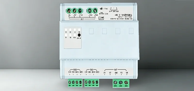
0-10V dimming output module
0-10V dimming output module — 0–10V dimming output with welcome and sleep curves via RCU. 0–10V dimming module with welcome and sleep curves; actuator layer for downlights and strips.
- 0–10V dimming output
- Welcome and sleep curves
- Downlights and strips
- RCU actuator module
RS485 0-10V dimmer module
RS485 bus Modbus RTU · with RCU networking
Installation DIN rail / low-voltage cabinet
Load confirm model selection per project
Application hotel guestroom · building public areas · centralized control
- Product
- Dimming module
- Series
- Dimming
- Features
- RS485· dimming
- Interfaces
- RS485 bus · Modbus RTU (model-dependent)
Specifications
| Parameter | Specification |
|---|---|
| Product name | Dimming module |
| Product series | dimmer module |
| Key features | RS485· dimming · 0–10V/SCR dimming · RS485 bus · LED/halogen load · scene dimming linkage |
| Product overview | Dimming module — 0–10V dimming output with welcome and sleep curves via RCU. RS485 bus actuator, DIN-rail mount, pairs with hotel RCU host. |
| Installation | 86 mm back box / standard wall / LV cabinet (model-dependent) |
| Communication method | RS485 bus · Modbus RTU (model-dependent) |
| Delivery | Bulk project supply · finish and load per BOM |
| Applications | Hotel guestroom · building public areas · bulk projects |
| Engineering sup port | Detailed design docs · project BOM · bulk supply coordination |
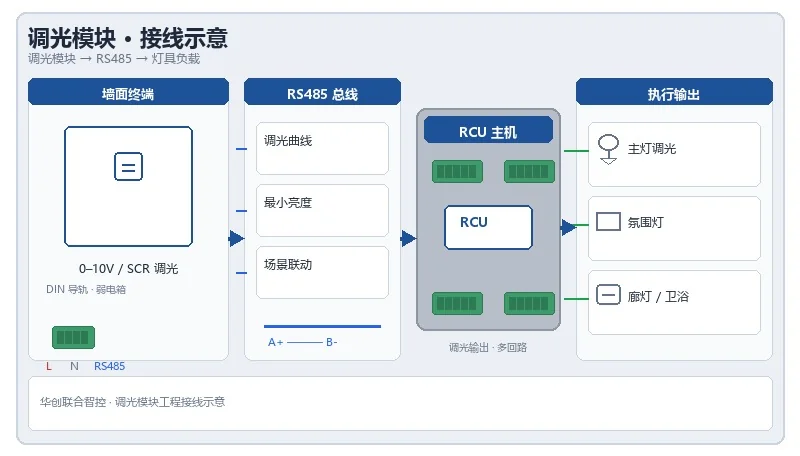
Wiring diagram
Dimmer module engineering wiring reference — 0–10V/SCR output and luminaire load matching. Per signed drawing set.
Installation notes
- module address must be at detailed design phase with RCU circuit schedule, scene schedule planned together
- DIN rail/low-voltage cabinet installation must reserved cooling space, terminals torque per factory specification
- Wire per project drawing; signed projects use factory shipment drawings
- after power-on with RCU commissioning: output actions, bus communication, scene linkage item-by-item acceptance
- Configure dimming curve and minimum brightness in RCU program
Downloads
Full datasheets, wiring diagrams and certificates are in the download center, or contact sales for project BOM.
Recommended for you


requires 0-10V dimmer module selection and dimming matching? Contact the team for dimming curve reference, load confirmation and project BOM.